Desiging a wooden holder for fitting Lynn Radeka’s pin-registration carrier system in the Durst 1200 enlarger
The pin registration carrier system from Lynn Radeka was what I was looking for getting a better control over the analogue printing proces. But when I tried to put it to work I found that it did not fit in my Durst 1200. The space of the enlarger was much wider than the height of the carrier system and thus it could move freely, and also it cannot be placed fully under the enlarger due to a metal pin in the back of the support table, defying the purpose of the pin carrier system. So I decided to make a wooden holder/shim for the carrier system. When I showed it to Lynn he was enthousiastic about the design and asked if I would share how I made it for other Durst owners. So here we go...
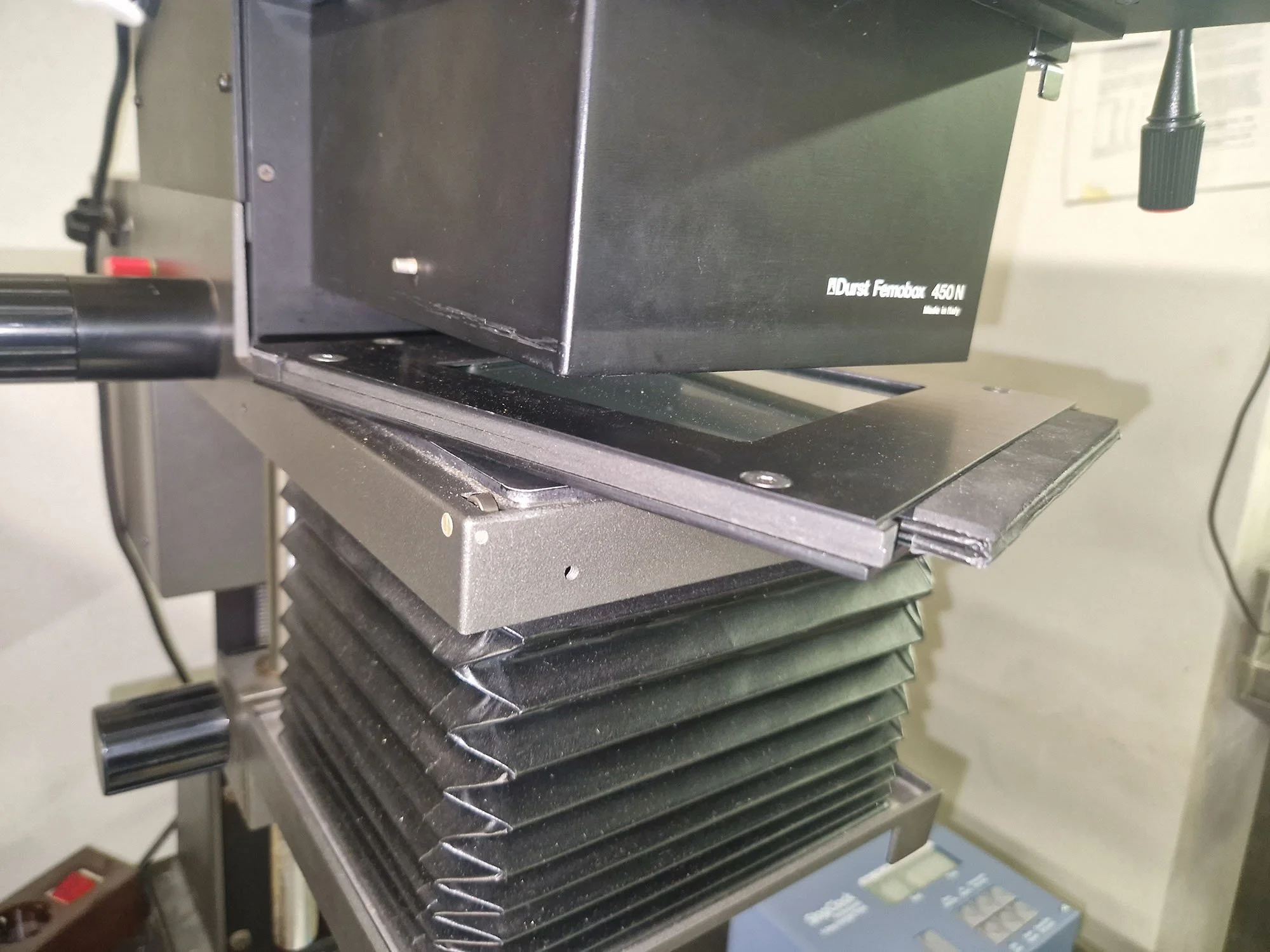
the metal holder of the pin-registration system is too small and there is a metal pin in the back of the supporting plate that prevents the positioning all the way to the back

the metal pin in the back of the enlarger preventing the carrier system to be fully inserted to the back.

the metal sleeve in the front side of the support table of the enlarger.
The original filmholder for the Durst 1200, the so called “Femoneg” has two fixation points that ensures exact repositioning of the Femoneg. It is well designed and slides in very smoothly. One fixation point is a small metal pin that is in the back of the supporting table under the light-mixing box (Femobox). The second fixation point is a small metal sleeve in the front of the supporting table. The Femoneg has a sleeve that fits the pin in the back and has a pin that fits the sleeve in the front. Because of this the glass plate in the Femoneg is a bit elevated above the supporting table and therefore the negative is also elevated. When designing you own holder these things are important to realize, because helps with the design of the holder.

the bottom side of the standard Femoneg negative carrier for the Durst with the sleeve for the backside pin and the pin for the frontside sleeve of the support plate
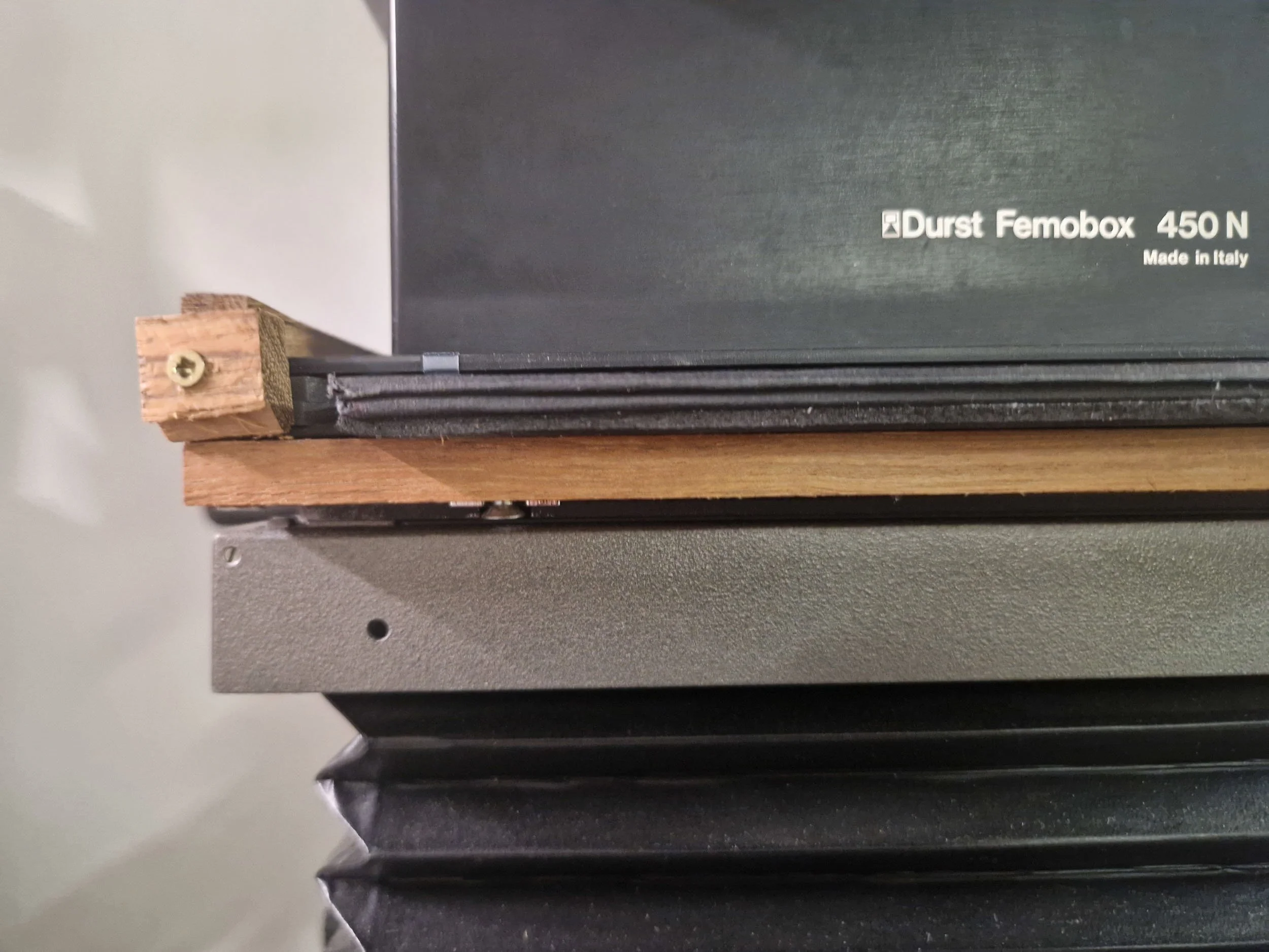
First you have to pick a piece of wood that allows to fit in the space under the enlarger with the pin carrier system on top of it. The thickness of the wooden slab in my enlarger can be about 10-11 millimeters before it hits the Femobox. A little space above the wood+pin carrier system did not prove to be a problem when using it in my enlarger. So my guess is that one should not worry too much about that.

the wooden slab+the metal holder of the pin-carrier system fitting close enough under the light-mixing Femobox
It is not relevant if the wooden plate sticks out a bit on the sides of the enlarger. It will not affect the repositioning. There are 3 items in the design that are relevant to ensure accurate repositioning. Those are: 1) the sleeve for fitting the pin in the back, 2) in the end result the backside of the metal holder should fit completely against the back in the space of the enlarger 3) the screw in the front that slides in the sleeve in the front.
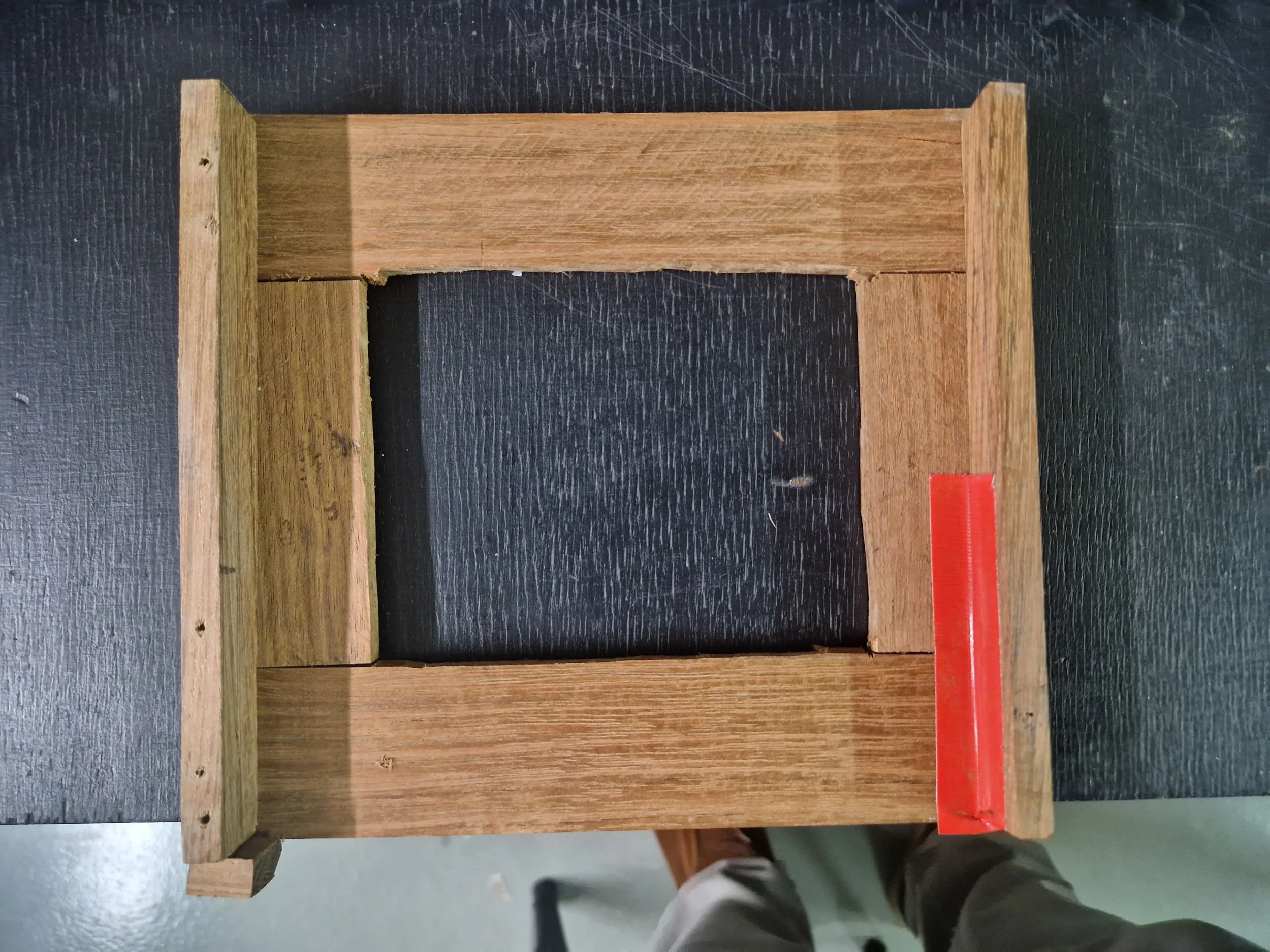
The wooden slab can be cut in 4 small wooden strips which are a approximately the size of the Femoneg. That is an easy template to use. The back and front sides of the wooden holder should consist of the long wooden strips and the side strips on the left and right should be the short wooden strips. By that the back side can be one long stretch that can be stable fitted to the back of the enlarger.

View to the backside of the wooden frame. Fitting the wooden strips over the Femoneg for dimensions. Also temporarily taping them together helps to make it easier to fix by screwing the upright small wooden strips to the frame. The back side of the wooden frame should be long wooden strips and should be straight to fit well to the backside of the enlarger.
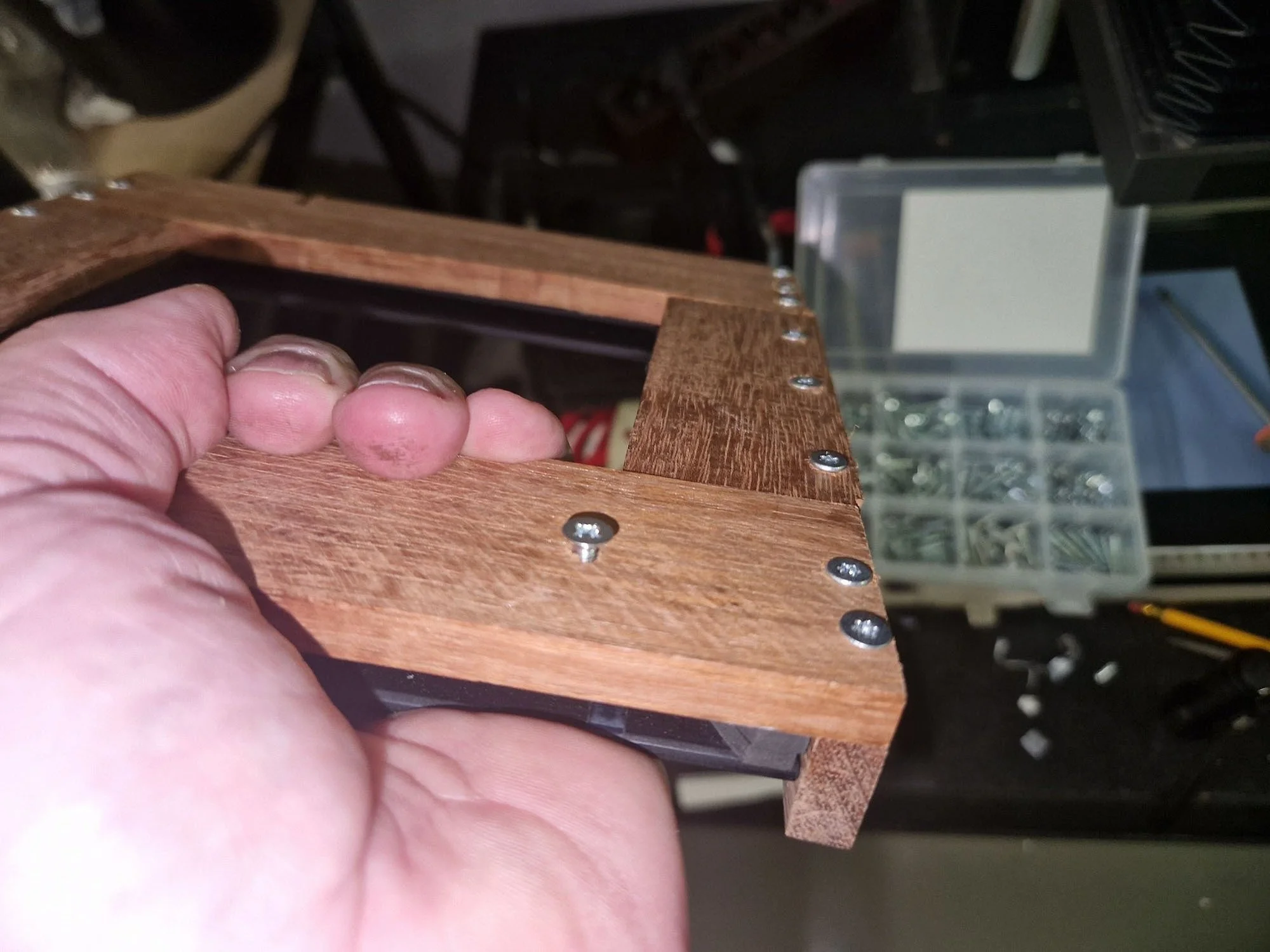
Two additional small wooden strips can be cut and fixed by screws upright/perpendicularly on the wooden frame. These small wooden strips will serve as an side support for the pin carrier system which should fit tightly in between. The small wooden strips should cover from front to the back of the wooden frame so that on each side it will fix the front strip, the side strip and the back strip. I used clamps to fix the small wooden strips perpendicular to the wooden strips for the frame. There is some leeway for placement of the first strip. It should be at a 90⁰ angle to the back side but is does not matter too much how far to the side the strip is placed. The placement of the second side strip should be rather precise. I placed the pin carrier system to the already fixed wooden strip and then positioned the second strip rather tightly to the pin carrier system and fixed it with a clamp and then placed the screws. This requires attention, time and patience to get the second small strip in the right position.

the bottom side of the wooden holder. The small wooden strip is clamped to the wooden frame and the screws are placed so that the upright strip is fixed to the three wooden strips of the frame
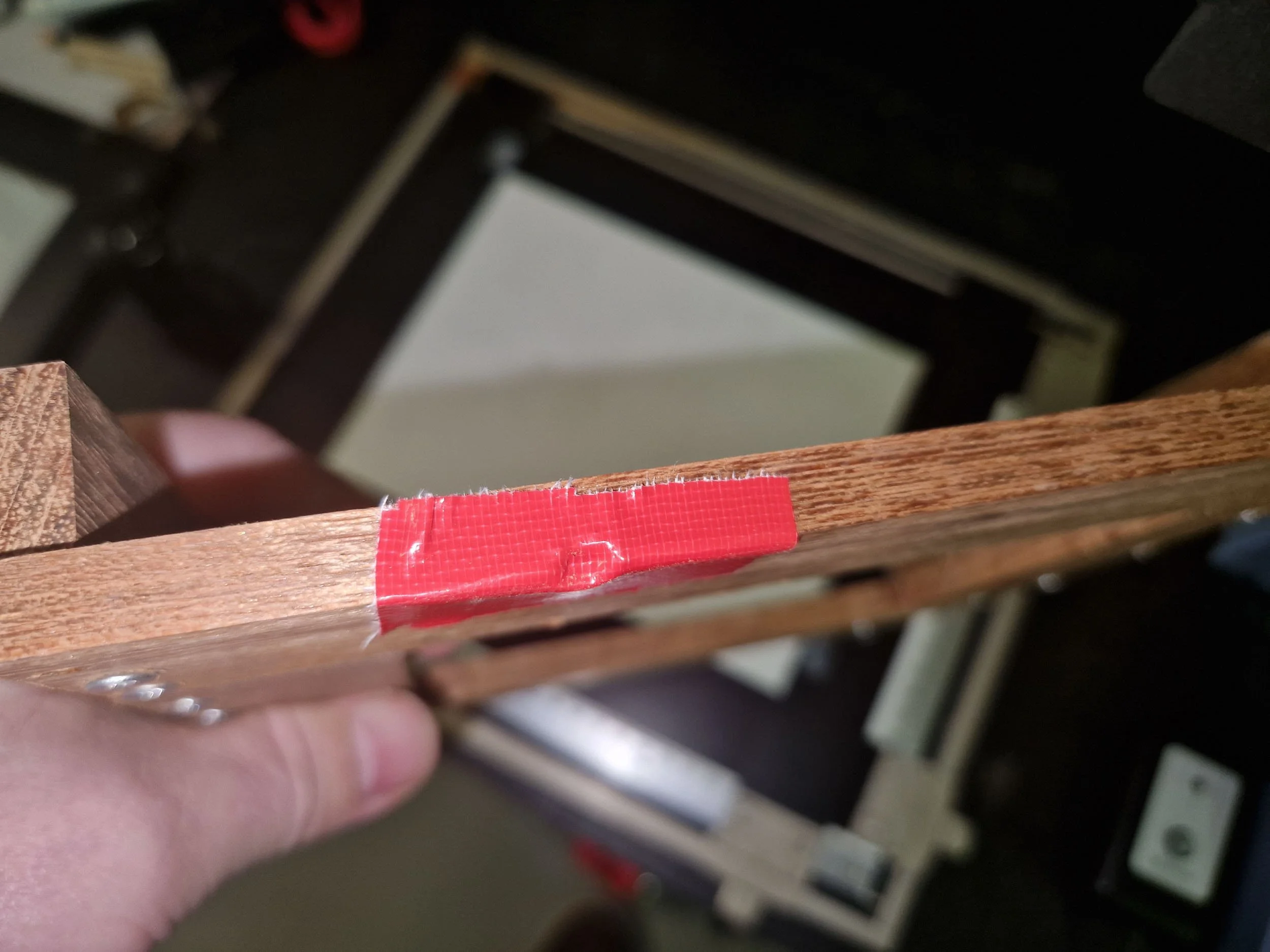
I had a small deviation in the front and solved that by adding a piece of (red) duck tape. After this the pin carrier system fits without any possibility of movement between the upright wooden strips. By the way, make sure that the pin carrier system is placed with the right side up while doing all this.
View from the upside of the wooden carrier. The upright small wooden strips are holding the frame together. The red duck tape was added to make the metal pin carrier system fit tightly.
When these are fixed the wooden frame is ready. The square open space in the centre of the holder should be a bit larger than the size of the glass carrier plates so the wooden frame will not obstruct the image.

View from the bottom side. The center square space of the wooden holder should be smaller than the glass frame.

the pin registration system in the wooden holder. There is no movement possible of the metal frame in the wooden holder. It slides in from the back because of the stop on the front side.
The next step is to make the sleeve in the back side of the wooden strip that matches the position of the metal pin in the back, so the wooden frame will slide all the way in. I placed a small piece of red duck tape on the back of the wooden frame and pressed it firmly against the pin in the back of the enlarger so a dent would show in the tape. That is the position where the sleeve should be drilled. I used a drill size that corresponded to the width of the pin. When that is done the wooden frame should fit under the enlarger all the way in to the back of the enlarger and already should fit sort of stable positioned. The next step is to place a screw in the front side that will slide in the front sleeve. After this is done the wooden holder should fit tightly and sit quite stable under the enlarger.

stick a piece of duck tape (red) on the back edge of the back side of the holder and press hard against the metal pin on the support table of the enlarger to get a dent.
a dent in the tape, indicating the location for drilling the sleeve.

the sleeve drilled in the back wooden strip to fit over the metal pin in the back side of the support table in the enlarger
the placement of the screw in the front strip to fit the sleeve in the front side of the support table.

the back side of the enlarger. The frame fits to the back side of the enlarger so there is no movement of the carrier system.
I added a small wooden piece as a stop in the frontside that retains the metal frame of the pin carrier system but allows that the glass carrier plates can be removed from the metal frame from the carrier system. This prevents that the metal frame will not be pulled out in the dark when the glass carrier plates needs to be taken out.
the small wooden front stop screwed to the wooden holder that holds the metal frame but allows removal of the glass carrier plates. Also the fixation screw is visible here fitting in the front sleeve.
It is a simple desing and without a smooth finishing. I have used this system for a number of prints and it works rather well. I am able to replace the glass carrier system in the metal holder after adding of removing masks during printing. Here below an example of how precise the system can be. On the left the original photo (scanned 4x5 negative), in the middle the mask and on the right the scanned analogue B&W print.


